MQXF Presentation
- Outline of magnet assembly
Four coils shall be assembled together, with the Al collars, and with the iron pads, bolted around the collars (see Figure 5). This assembly constitutes the coil-pack sub-assembly.
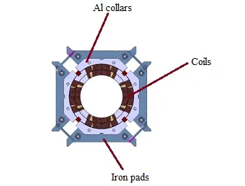
Figure 5: Coil-pack sub-assembly
- Shell-yoke sub-assembly
The second mechanical assembly of the magnet is the shell-yoke sub-assembly, whose fabrication involves the following steps (see Figure 6):
- Assembly of the iron yoke packs from laminations;
- Alignment and assembly of the iron yoke inside the aluminium shell to form 5 shell-yoke modules;
- Alignment and assembly of the 5 shell-yoke modules into the full shell-yoke sub-assembly.
Figure 6: Shell-yoke sub-assembly: iron yoke packs in the Al shell (left), 5 shell-yoke modules (center) and final shell-yoke subassembly (right).
This shall involve the following steps:
- The coil-pack is inserted in the shell-yoke;
- 16 4-m-long bladders are inserted (8 per magnet side);
- An azimuthal pre-stress of the order of 100 MPa is given and kept by appropriate loading keys.
Axial loading shall be given through the end plates fixed through bullets to the axial rods. An axial force of 1.2 MN after cool-down is required. The splices between the four poles shall be done in the connection box. After this operation the magnet shall be prepared for shipping.
The cross-section of the ground insulation scheme is shown in Figure 12 (green lines) and is composed by a layer of 0.125 mm polyimide covering the coil outer radius and the mid-planes, and by 2 layers of 0.125 mm polyimide covering the collars.
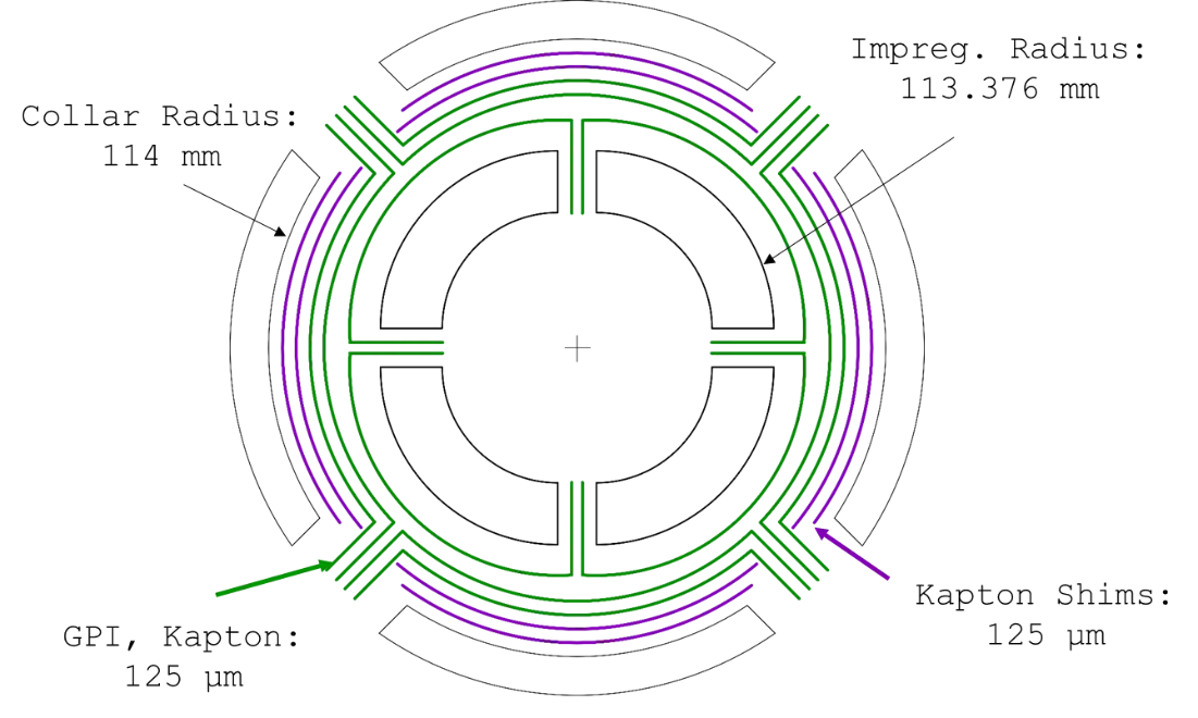
Figure 12: Ground insulation scheme.
The alignment of the coil with respect to the structure is ensured by a alignment key, inserted in the coil poles and locked by thick-lamination bolted collars (see Figure 13). It is made of G-11.
Figure 13: Pole alignment key, inserted in a pole slot, and locked by the collars.
The first mechanical component, moving from the bore outwards and after the coil, the pole alignment key and the ground insulation, are the aluminium collars (see Figure 14). They are composed by laminations 50 mm thick. The locking system is based on bolts. As a result, one half of the collars features a threaded hole (threaded collars), and the other half features the countersink for the rod (countersink collars). At the extremities, the collar thickness is adjusted to match the overall magnet length, both in the connection side (extremity CS, threaded or countersink, collars) and in the non-connection side (extremity, threaded or countersink, collars). They are made of Aluminium EN AW-6082-T6 according to EN 573-1 and EN 515.
Figure 14: Bolted collar laminations.
The pads constitutes the outermost components of the so called coil-pack sub-assembly (see Figure 15). The pad stacks are composed by thin iron laminations, placed in the straight section, thick iron laminations, placed also in the straight section and aimed at bolting the pads around the collars, and thick stainless steel laminations, placed in the ends to reduce the peak field in the coil heads. They are made of pure iron (Fe 99.99%) and austenitic steel EN 1.4404 or EN 1.4435 according to EN 10027-2, equivalent to AISI 316L.
Figure 15: Coil-pack sub-assembly including pads.
In between the yoke and the load pad laminations, two plates, called masters are inserted (see Figure 16). The masters include three narrow slots for the insertion of loading and alignment keys and two wide slots for the insertion of water-pressurized bladders, which provide the pre-load to the superconducting coils at room temperature. They are made of pure iron (Fe 99.99%).
Figure 16: Coil-pack sub-assembly with masters.
The yoke stacks (see Figure 17) are composed by thin iron laminations, placed in the straight section of the aluminium shell segments, and thick iron laminations, placed at the extremities of the shell segments. They are made of pure iron (Fe 99.99%).
Figure 17: Yoke laminations.
The Al shell is the mechanical element that balances the transverse electromagnetic forces during magnet powering. Each magnet has a shell subdivided in 12 parts: two short shells (410 mm) at the extremities of the magnet and 10 long shells (800 mm) in the central part of the magnet (see Figure 18). The shell is made in aluminium EN AW-7175 according to EN 573-3:2013 but EN 515:1993 is acceptable with a heat treatment T74 according to ASTM B247. The material shall reach class 3 of EN 4050 4:2012 or class B according to ASTM B594 – 13.
Figure 18: Shell segments.
The pre-load provided by the bladders is locked by two stainless steel keys, placed in between the two masters. A central bronze key maintains the alignment between the two masters. In addition, temporary keys are inserted during the assembly phase in between the yoke laminations, in correspondence of the 45 degree angle. They are made of Stainless steel 304L, black steel, Bronze.
In order to correct field quality errors, in particular non-allowed harmonics, iron bars can be inserted in the bladder slots after assembly and loading of the magnets. An example is shown in Figure 19. These ferromagnetic shims can correct up to ± 5 units of b3/a3, ± 5 units of b4 and +-1 unit of a4. They are made of pure iron (Fe 99.99%).
Figure 19: Magnetic shim locations of the short model MQXF1c, MQXFS3a, MQXFS5a.
The end plates, together with the axial rod, is the mechanical element that balances the longitudinal electromagnetic forces during magnet powering (see Figure 20). Each magnet has two different end plates, on the connection and on the non-connection side. They are made of stainless steel type XM-19.
Figure 20: View of the axial support system with end-plate and axial rods (left) and of the connection box (right).
The axial rod, together with the end plates, is the mechanical element that balances the longitudinal electromagnetic forces during powering. Each magnet has four axial rods. They are made of austenitic steel.
Other rods are needed to stack the iron, load-pads and collars. They have different diameter, ranging from 6 mm (collars) to 12 mm (load-pad) to 20 mm (yoke, of three different lengths). Each magnet has eight rods of each type. They are made of austenitic steel.
- Connection box
The leads of the four coils are connected in series at the connection side within a connection box (see Figure 20).
-
- Instrumentation
-
The aluminium shell and the axial rods will be instrumented with strain gauges provided by CERN. The aluminium shell gauges will be removed before stainless steel welding. The coil will be instrumented by fiber optics provided by CERN.
The assembly tooling is aimed at performing the following 3 main steps
- Assembly of the coil-pack sub-assembly;
- Assembly of the shell-yoke sub-assembly;
- Insertion and loading of the coil-pack inside the shell-yoke sub-assembly.
The following assembly tooling shall be utilized to perform the steps mentioned above:
- The four coils of the magnet shall be covered by the ground insulation. The tooling to form the ground insulation (left) and to install it on the coils is shown in Figure 27.
Figure 27: Tooling to form the ground insulation (left) and to install it onto the coils (right).
- The four coils are then lifted (Figure 28) and rotated (Figure 29) to prepare for the coil-pack assembly.
Figure 28: Tooling to lift the coils.
Figure 29: Tooling to rotate the coils
- The coil pack is then assembled (Figure 30).
Figure 30: Tooling to assemble the coil pack.
- In parallel, yoke laminations are stacked together (Figure 31) and inserted in the yoke-shell sub- modules (Figure 32).
Figure 31: Tooling to stack the yoke laminations.
Figure 32: Tooling to insert the yoke laminations into the shell sub-modules.
- The yoke-shell sub-modules are then combined together to form the yoke-shell sub-assembly, and the yoke pack, previously lifted (Figure 33) and placed in front of the yoke-shell sub-assembly , is inserted to perform the bladder operation (Figure 34).
Figure 33: Tooling to lift the coil-pack.
Figure 34: Tooling to insert the coil-pack
- Strain measurements during loading
The pre-loading of the magnet at room temperature shall be monitored with strain gauges. They shall be installed on the external surface of the aluminium shell, on the bore surface of the coil winding poles, and on all four aluminium axial rods. CERN will provide and install the gauges, and the acquisition system.
- Aluminium shell :
- Three aluminium shells, one in the connection side, one in the non-connection side, and one in the centre (see Figure 38), shall be equipped with four half-bridge strain gauge stations. They shall be located 90◦ from one another, along the outer circumference of the central cross-section of the shell, starting from the 15◦ above the magnet mid-plane. Each half-bridge is temperature compensated with an additional one, which is glued on a floating aluminium sample. The strain is measured in two directions: azimuthal (εθ) and axial (εz).
Figure 38: Longitudinal position of strain gauges.
- Coil winding pole :
- The four coil winding poles are equipped with three half-bridge strain gauge stations each. These stations are located in the connection side, in the non-connection side, and in the centre. Each station is temperature compensated and it measures two directions: azimuthal and axial.
- Aluminium Axial Rods
- Each aluminium axial rod (see Figure 39) is equipped with one full-bridge strain gauge station. They do not require any additional temperature compensation and are measuring the strain only in the axial direction.
Figure 39: Axial support system (short model case).
Measurement of the room temperature multipoles shall be performed (i) after coil-pack assembly and (ii) after transverse and axial loading. They will be jointly analyzed by CERN and by the contractor to validate the final assembly. The measurement consists of current plateaus at ±20 A during which the magnetic field is measured. The measurements at room temperature are aimed to verify the correct positioning of the coils and the magnetic properties of the components. Magnetic measurements are a holding point of the production. The joint analysis shall be carried out within 5 days, giving either OK for next manufacturing steps or requiring for corrective actions, which can include coil disassembly.